ProVI Product features – All important functions at a glance
The key ProVI features at a glance.
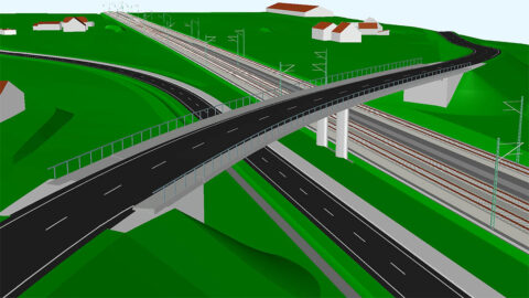
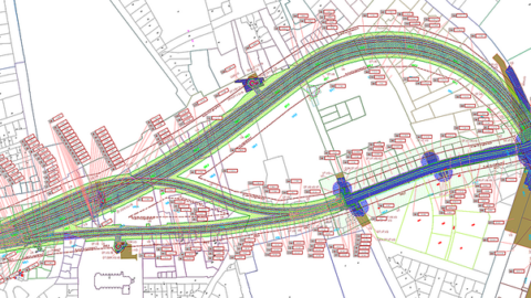
Alignment
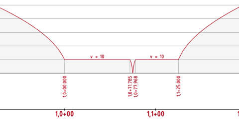
Design your alignments in ProVI, graphically and interactively directly in the site plan. The smart alignment elements remember how they were designed. This makes changes much easier to implement because the adjacent elements are automatically recalculated, so that all logical relationships are retained. The feature alignment is available in ProVI Road and ProVI Rail.

- Alignment references:
Establish dependencies between various alignments
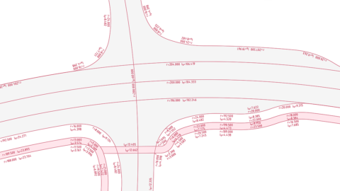
- Transition curve types:
Numerous transition curve types have been implemented in ProVI Rail
- Guideline compliance checking in real time:
Design alignments in compliance with the rules

- Switches:
Join switches, crossings, and slip crossings with other alignment elements, prevent position errors
- Existing alignments:
Reconstruct existing alignments from measured track points

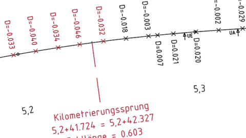
- Station jumps
for any ProVI alignments by entering missing or excess lengths
- Line optimization:
Calculate the permissible speed for individual route elements, determine the round-trip time for the line
- Routing in compliance with guidelines
- Visualization:
Adaptable for each project according to DB, ÖBB, and RE regulations or other guidelines
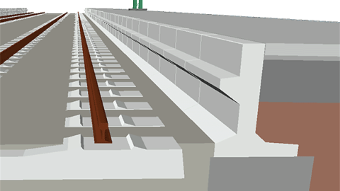
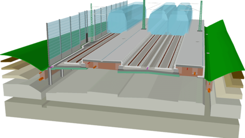
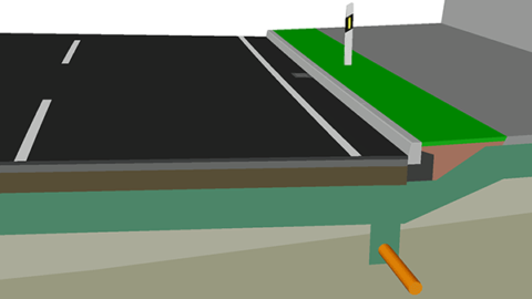
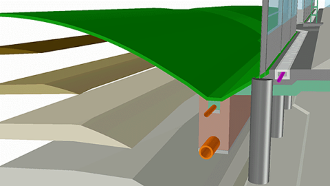
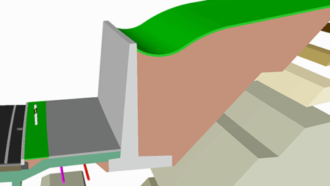
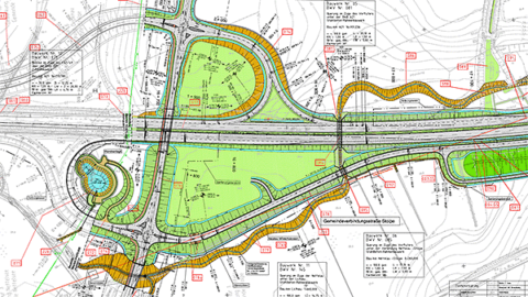
Platforms
Outer and central platforms are planned within the route model in ProVI. You can model the platform edge complete with coping stones and foundations, the platform surface, layer composition, platform drainage (box gutter or concrete gutter) and, for outer platforms, the rear side with angle support or non-raised curb. Platform fixture elements can be planned and positioned as well. The feature platforms is available in the Rail product.
- Guideline-compliant platform edges:
Calculation of the 3D curve for the platform edge, modeling of existing platforms
- Tactile paving system:
Planning of the tactile paving system for the visually impaired with no interface losses
- Revit interface:
Transfer the platforms generated in ProVI to Revit, export the tactile paving system and the platform fixture elements
External models
Since it is BIM software, ProVI handles the import of IFC and CityGML models from other specialist applications, for example, to integrate existing structures or bridge models into the building model.
- Collaboration with other project participants working on a shared building model
- Interfaces to consolidate the submodels from various specialist applications, forming an overall model
- Enrichment of projects planned in ProVI, for example, with surface construction planning from Revit and city models from GIS applications, visualization of these external models as interfaces in the route cross sections
- Attribution:
Editing of the supplied attributes, addition of new attributes
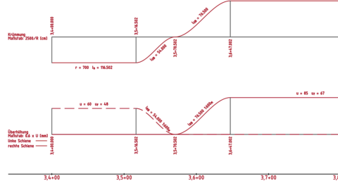
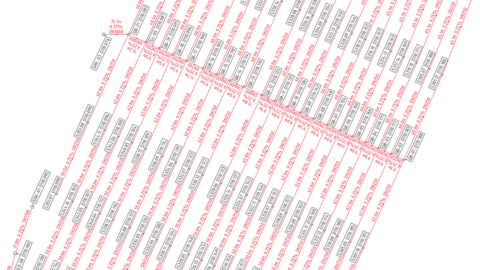
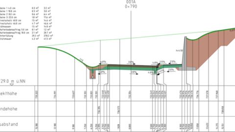
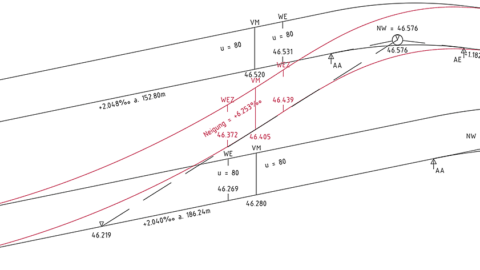
Vertical alignment
Vertical alignment establishes your route’s vertical profile, influencing the three-dimensional line layout, route structure, and the cut mass and filling. The feature vertical alignment is available in ProVI Road and ProVI Rail.
- Graphical design:
Interactively edit the vertical alignment in the site plan and longitudinal section, or by entering the points of vertical intersection into a list
- Guideline compliance checking in real time:
Design a vertical alignment in compliance with the rules
- Station alignment:
Choose the alignment for the calculation of station differences, vertical curve lengths, and tangent slopes
- Volume adjustment:
Ad-hoc volume calculation
- Existing vertical alignments:
Reconstruction of the existing vertical alignment from measured elevations
- Visualization:
Simultaneous visualization of multiple vertical alignments and longitudinal profiles in the grading plan, forced points
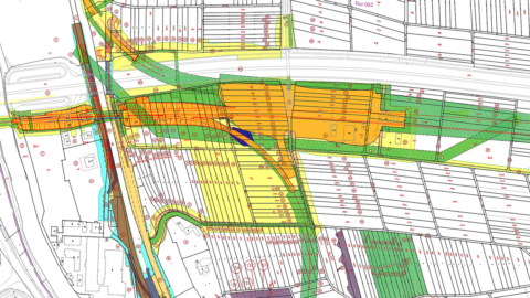
Land acquisition
With ProVI, you can import owner, land register, and cadaster data from ALKIS, calculate acquisition areas and create land acquisition plans and records. The feature land acquisition is available in ProVI Road and ProVI Rail.
- Import of plot data from OKSTRA, ALKIS files, various ALB formats, or CSV files, interactive drawing preparation, assignment of parcel numbers, calculation functions, and check routines
- Determination of acquisition areas through the intersection of the parcels with the required areas
- Generation of land acquisition records and plans according to DB, ASFINAG, or RE regulations
- Export of parcel and land acquisition data via the OKSTRA interface or CSV files, IFC output of the required areas
Sewer planning
Use the ProVI sewer program to conveniently design and evaluate the drainage strategy for traffic routes as well as complete wastewater networks. The feature sewer planning is available in ProVI Road and ProVI Rail.

- Sewer design:
Drainage planning with the interactive graphical sewer editor in the context of the overall model, calculation and check functions, use of component catalogs
- Calculation:
Manhole lists and drawings, hydraulic calculation with consideration of sewer segment-specific catchment areas, mass and volume calculation
- Visualization:
Visualization of manholes, sewer segments, and ditch layers in cross sections, site plans and grading plans, three-dimensional visualization of the sewer network with solids
- Data exchange:
ISYBAU interface for the import and export of drainage data, export of an attributed 3D model of your drainage network as an IFC or CPXML file
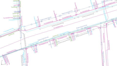
Supply lines
Road and rail construction work always affects the supply lines located in the vicinity. Our CAD software allows you to see these in the context of the overall model. This helps you identify potential conflicts with your plans in the design stage. The feature supply lines is available in ProVI Road and ProVI Rail.
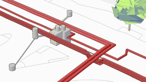
- Supply line editor:
Record and edit supply lines for utilities such as electricity, telecommunications, water, gas, or district heating in a graphical, interactive interface, along with the definition of all manner of supply line and junction types
- Existing drawings:
Extraction of existing supply lines from existing drawings
- Visualization:
Visualization of junctions and supply lines in cross sections, the site plan and grading plan, three-dimensional volume model
- Data exchange:
Export of an attributed 3D model as an IFC or CPXML file, or via additional interfaces
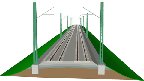
Catenary
Use ProVI to manage and edit the catenary masts complete with foundations and cantilever beams. You can enter the positions and elevations of masts either in the form of fixed coordinates or relative to a track alignment. Data from specialized programs for catenary planning, such as OLACAD, can be transferred to the ProVI model via interface files or from drawings. The feature catenary is available in ProVI Rail.
- Evaluation options:
Visualization in cross sections, the site plan and grading plan, three-dimensional volume model
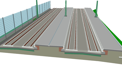
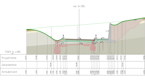
Cross section editor
Describe the roadway or railroad in the route with surprising ease using a fully parameterized 3D model. In railroad construction, you first model the track superstructure with the rails as a ballasted track, solid track, or tramway line. In road construction on the other hand, you generate lanes with the width and transverse slope progression as well as the underlying layer composition. The cross section editor is available in ProVI Road and ProVI Rail.
- Flexible building blocks:
Compressive catalog of standard cross sections
- Integrated specialist trades:
Generation of the route model with data from terrain models, subsoil, sewers, supply lines / utilities, catenary, or external models
- Parameterized and clearly arranged:
Use of flexible components with dimensions that can be variable within the route
- Rule-based and up to date:
Definition of the parameter values and existence of objects using rules, automatic adjustment of the route in case of changes
- Smart and fast:
Automatic adaptation of the smart components
- Animation:
“Drive” along the route while editing in the cross section view
- Bundling of multiple routes in a route project for the joint evaluation and visualization of various traffic routes
- Evaluation:
Determination of the masses and quantities from the route model according to REB, transfer to third-party programs for evaluation
- Visualization:
Derivation of visualizations for cross sections, the site plan and grading plan, 3D visualizations, three-dimensional volume model
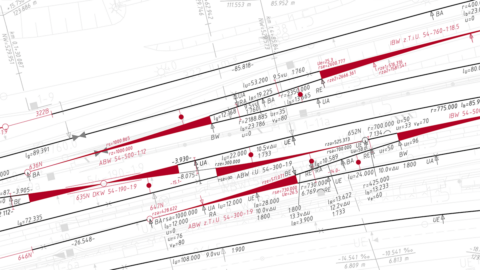
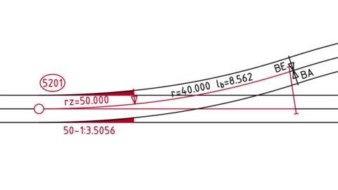
Switches
Switches in ProVI are part of the branch alignment and can be positioned at any point along the main track – on a straight line, arc, or transition curve. Likewise, crossings and slip crossings are part of the intersecting alignment and can be positioned as required on straight lines and curves. The feature switches is available in ProVI Road and ProVI LST.
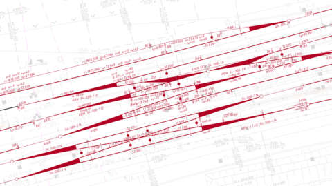
- Dependencies:
Efficient handling, also for extensive track planning, since any number of alignments can be edited simultaneously and joined
- Position error are prevented because the switches are automatically re-integrated when the tracks are changed
- Connection switches:
Precise calculation of the switch position
- Existing switches:
Automatic positioning of existing switches in imported or re-routed alignments, adaptation of the switch triangle when needed
- Track connections:
Automatic calculation of single crossovers and switch tracks among multiple tracks
- Blade construction:
Individual composition of tramway switches from standardized blade constructions and variable end pieces
- Preparation of a switch grading plan according to DB guideline 885.1102
- Clearance points:
Automatic calculation of the clearance point position
- Comprehensive switch catalog with switches, crossings, slip crossings, and blade constructions according to the following guidelines:
– Germany: DB Ril 800.0120, VDV BOStrab, Obri-NE, Ril Münchener U-Bahn
– Austria: Voestalpine switches
– Switzerland: SBB I-22046, VöV RTE 22564
– Netherlands: OVS00056
Guidelines
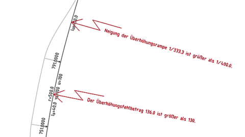
ProVI actively assists you with the guideline-compliant routing of your roadways and railroads. Easily design guideline-compliant alignments, vertical alignments, and switches. Minimum, standard, and maximum values for element lengths, radii, and banking are automatically calculated for you if desired. Conformity with the guidelines selected by you is checked in real time even during the design phase. Positions are marked immediately in case of violations. The limit values to be checked are usually read from a configuration file, which means they can be adjusted by the user if needed.
- Road guidelines:
– Germany (RIN, RAL, RAA, RASt, RLW, ERA)
– Austria (RVS)
– Czech Republic (CSN 736101)
- Rail rules and standards:
– Germany (Ril 800, BOStrab, Obri-NE)
– Austria (RW 01.03, HL guideline, B52)
– Switzerland (SBB I-22046, VöV RTE 22546)
– Netherlands (OVS00056)
– Romania (NP109, I314)
- Cross section guidelines:
Help with the design of compliant cross sections using calculation tools or with the selection of standard components from the guidelines
– Standard profiles for roadways, ballasted tracks, solid tracks, and tramway tracks
– Roadway/railroad widening calculation
– Transverse slope calculation for roadways / railroads and shoulders according to RIN / RAS
– Design of RAL intersection types
– Calculation of stopping and passing sight distances according to RAL, RVS
– Calculation of blind areas according to HViSt 2008
– Marking lines according to StVO, RVS 05.03.11
– Automatic calculation of the subgrade level width and slope according to DB guideline 800.0130
– Minimum clearance outlines according to DB guideline 800.0130
– Positioning of cable troughs according to DB guideline 800.0130
– Platform edge calculation according to DB guideline 813 / ÖBB guideline RW 01.06
– Volume calculation according to REB 21.003 / 21.033
- Plans:
Guideline-compliant generation of site plans, longitudinal sections, and cross sections, e.g. according to RE, DB AG